I got myself an Elm327 V1.5 but I found that it will not work on J1850 VPW J1850 PWM protocol especial for most Fords. But it did work like a charm on cars.
My idea came from a post in mondeoklubpolska.pl/ forum. Thanks Atom from Poland. I got the post translated into English, then I tried it out on my 2001 MK3 duratec 1.8 and it works like a charm. So I make my new version.
I have to confirm that the method only fits for elm327 V1.5 as mine and I have no responsibility if your elm327 is blow up or broken.
Equipment needs:
Screw driver
Knife
Solder iron with very small bit and solder
About 10 mm of insulated small-gauge wire
Then do as follows:
1) Peel off the cover of the elm327 main unit and remove the four screws by using screw driver, take these out and set the box apart.
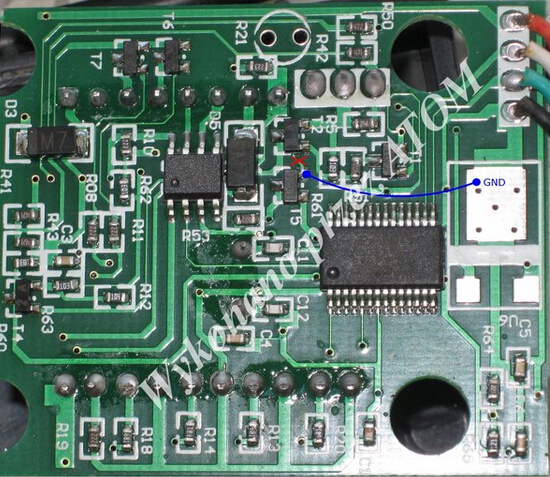
2) Check the elm327 inside is like this
3) You will notice that there is a PCB tack running between T5 and T2 there. Hook up a multimeter to check the continuity between the emitter of T5 and the emitter of T2 (on the side with two legs). If there is continuity, you should use the knife to cut between T2 and T5 as shown in red below.

4) Check between the emitters of T5 and T2 to make sure there is no continuity any more.
5) Solder a short length of wire between the emitter of T5 and the emitter of T1 or Pin1 of the output connector. Be carful not to apply too much heat to T5 and T1.

6) Again use the multimeter to test the continuity between T5 and Pin1 output connector. Ensure there is stable continuity.
7) Reassemble the elm327 main unit and try to test on J1850 PWM system.
The job is done.
